
We started this blog to document our travels; travels that take us almost anywhere in our truck camper. Many times that means we’re off grid and to be off grid means storing power. Many folks talk about how much solar they have which sounds good but if you don’t also have the right battery storage capacity the incoming solar has no where to go! Our current solution provides 760W of solar (4 @190W) and 17.5kwh of battery. We depleted our battery once since it’s been on the Lance camper. That was spending nearly 2 weeks in Canadian cloud and tree cover. Now, we also have a 2nd alternator on the truck to provide a backup charging source. In the new expedition build, we are eliminating propane and our electric power consumption will increase. The battery size will remain the same and we will add an additional solar panel for a total of 5 panels (950W) of solar.
The Lance camper we have now was was always intended as a test bed. We first needed to test us. Will a truck camper provide us enough space to travel multiple months and seasons at a time? Second test was to prove out the power system Steve envisioned. Steve had specific ideas of how best to build a mobile, off grid home on wheels and he used the Lance to prove out his power build. Once we proved the system, it would become part of our planned expedition vehicle on the Ford F350 and eventually a M1088A1 5 ton tractor.
The power system has been in operation since August 2018, yet we never documented the details on the blog. Now that we’re building the expedition camper on the F350 and this power system will be migrated to the new camper in a few weeks, I thought it was a good idea to make the current system details available for anyone who’s interested.
What’s in this power system
The electrical test bed system consists of:
- Battery: 17.5kwh in 140 lithium manganese oxide cells (16Ah/3.75V/cell) in 7S20P, (21-29.4V)
- Inverter: 4kw/24V Samlex EVO4024, 110% surge for 30min., 130% surge for 1min.
- AC charger built into the inverter: 105A max. programmable
- DC charger: 150A (not continuous) modified, voltage regulated vehicle alternator
- Photovoltaic panels: 4 – 190w polycrystalline, 24v in 2 tilting mounts
- Battery Management System (BMS): Electrodacus SBMS120 w/ integrated solar controller
- DC-DC Buck Converter: 20-35V to 13.8V@40A.
- Auto-transfer switch: 120V@60A integrated into the inverter. Manages generator, grid, and inverted AC
First, some terms:
BATTERY is a series of cells or packs, connected in series and/or parallel arrangements to increase voltage or capacity. There are two batteries referenced, the original leaf and the to be constructed camper battery. In some cases, the inference is needed to determine which one is addressed.
PACK is specific to this situation and refers to the original Leaf configuration which produced a ‘sardine can’ containing 4 pouch cells connected 2S2P.
CELL refers to the single pouch cell inside the 4 cell battery pack.
What makes up the camper battery
The camper battery is built from packs salvaged from a used 2015 Nissan Leaf electric car battery. The Leaf battery is comprised of 48 lithium manganese oxide packs, each containing 4 cells, internally connected 2 in series and 2 in parallel (2S2P).
The packs are rated at 32Ah@7.5V. In the car, the 48 packs are series-connected resulting in a 96S2P (32Ah/360V) battery. Because each pack has 2 cells in series and I need to end up with 7 cells in series, I need to open some packs and break the series connection to produce some 1S4P packs. The camper battery requires what is effectively 3-1/2 packs in series pack to produce 7S.
Where does it all fit
In this experiment, physical space is the key driver. There is no space inside the camper or in storage compartments, so the pack needs to be externally mounted. Because I want the battery to remain with the camper when the camper is dismounted, the only practical place to externally mount it is on the camper bottom. The packs are about 1-3/8 thick and weigh 300 lbs. For ease of mounting and dismounting, a battery case will be made to attach to the camper bottom.
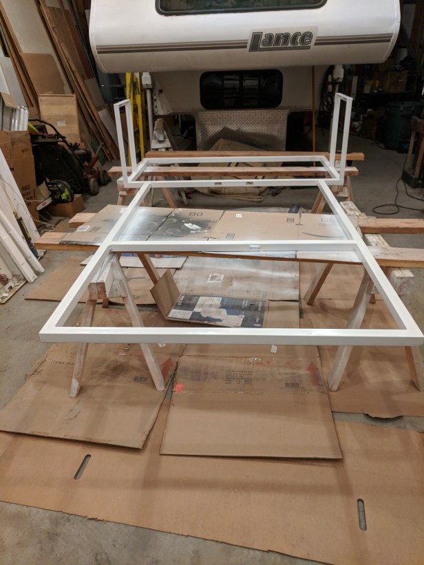
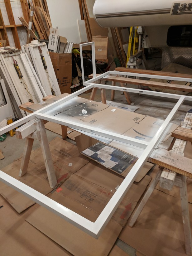
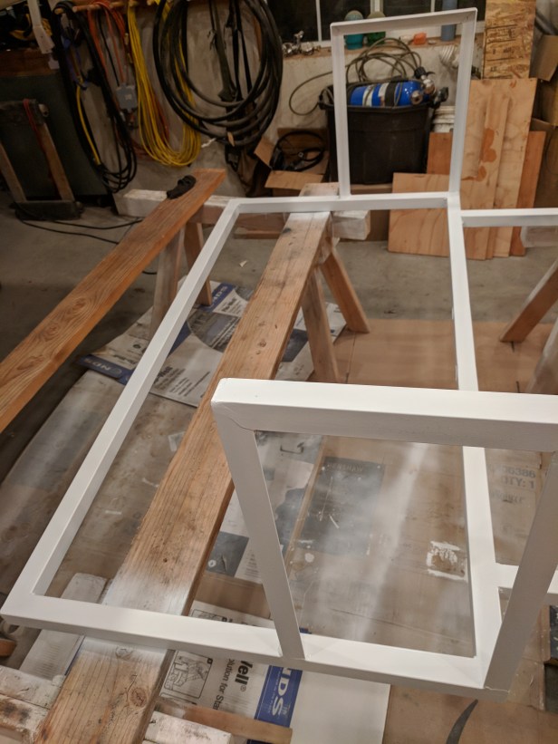
Since the entire weight of the camper rests on the pack, the structure must be strong so only the case supports the camper weight. This is a temporary installation so the camper must be able to accommodate it with minimal structural modification. Since this is an experiment, the camper battery may require periodic modification, so it will be readily removable (but I have never even opened it in 2 years of use). The photo below is of the nearly complete assembly and is shown here to provide an image of how the sub-assemblies will need to fit together.

The battery case frame is 1.5″ x 1.5″ x 16ga steel tube. The footprint is the portion of the camper which rests on the truck bed (plus a little). It is 48in wide in the front and 58in wide in the back. There is some slight additional footprint in case at the front of the (wider) rear portion where the angle frames stand up to provide cable ways and an equipment compartment.
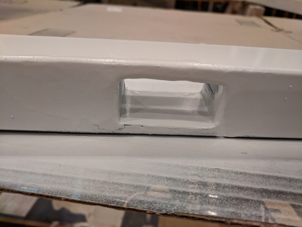
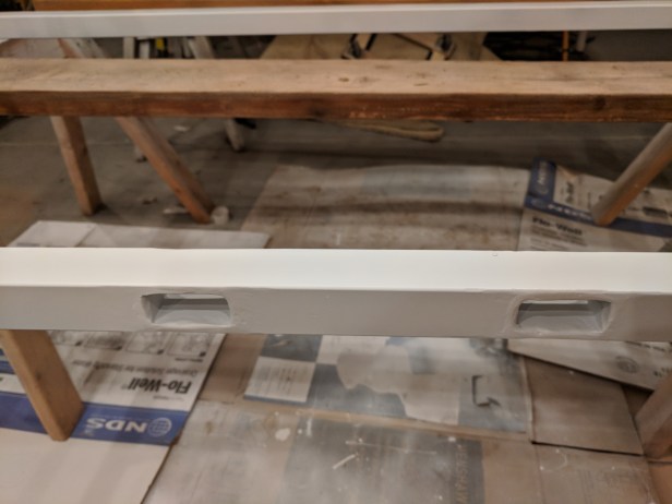
The tube frame is compartmentalized for parallel sets of batteries, requiring cable runs between them. Cables cannot run above the frame because the camper sits directly on it. Neither can they run beneath it because the 1/2in plywood bottom rests on the truck bed. Neither can they run beside it because the frame is only barely narrower than the space between the wheel wells. Cable pass-throughs are made by cutting through the 1.5 square frame and reinforcing with a 1.5″ long piece of 1″h x 2″w tube, fully welded and ground on both sides.
Because I want to be able to both fully detach the battery from the camper and be able to return the camper to its original condition, all cabling must be inside the battery case. Any connections to the camper must be readily disconnectable. To facilitate this, the wider, rear compartment extends forward of the camper footprint around 14in on the driver’s side and 10in on the passenger side. These extensions will become equipment boxes about 5″ deep with the driver’s side one being accessible from inside the camper and containing the BMS and other equipment.
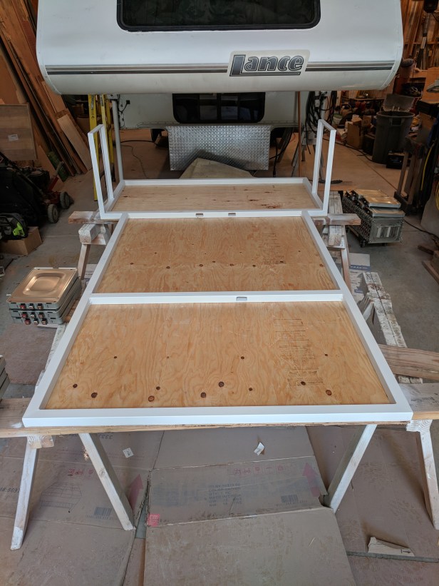
The bottom deck is 1/2in plywood with white enamel exterior paint, attached with self drilling truss head screws. The packs are mounted to the plywood using a 1/4-20 x 1-3/4″ long screw into a recessed T-nut. Below, they are test fit for mounting hole marking.

Battery Layout
The battery layout is in 4 groupings of packs (effectively my ‘3-1/2 packs’ in series). In the front compartment is one group of 10-2S2P packs. In the center compartment are 2 groups, a second 10-2S2P packs and one of 5-4P packs (this is the ‘half’). In the rear compartment is the final group of 10-2S2P packs.
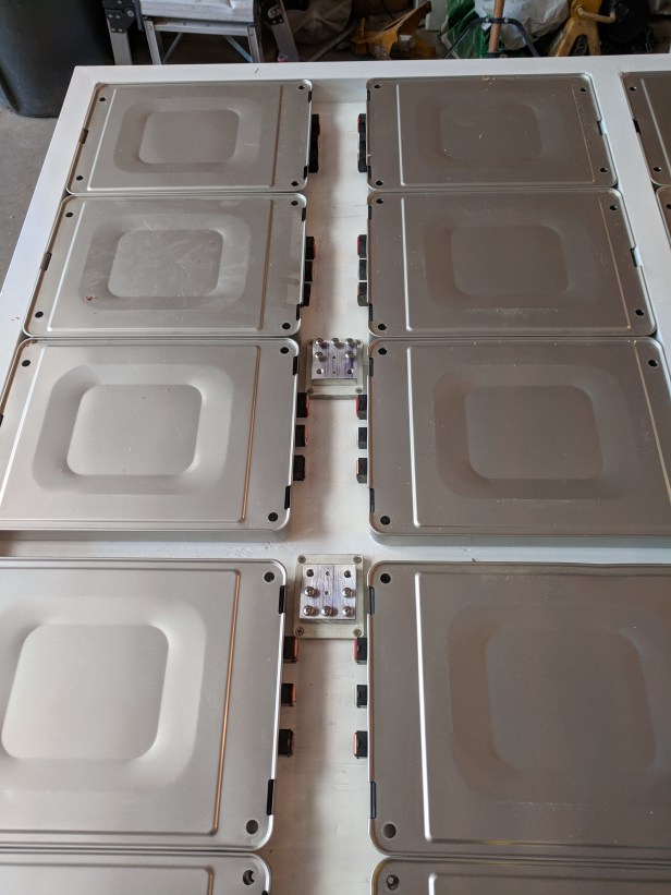
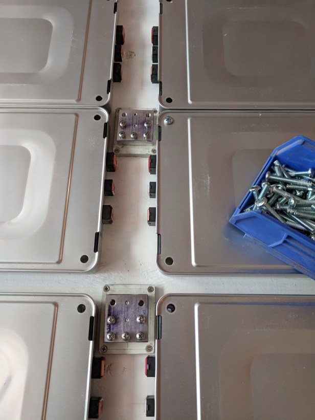
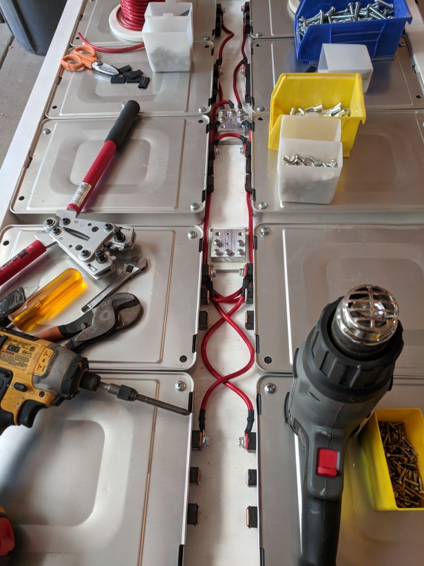
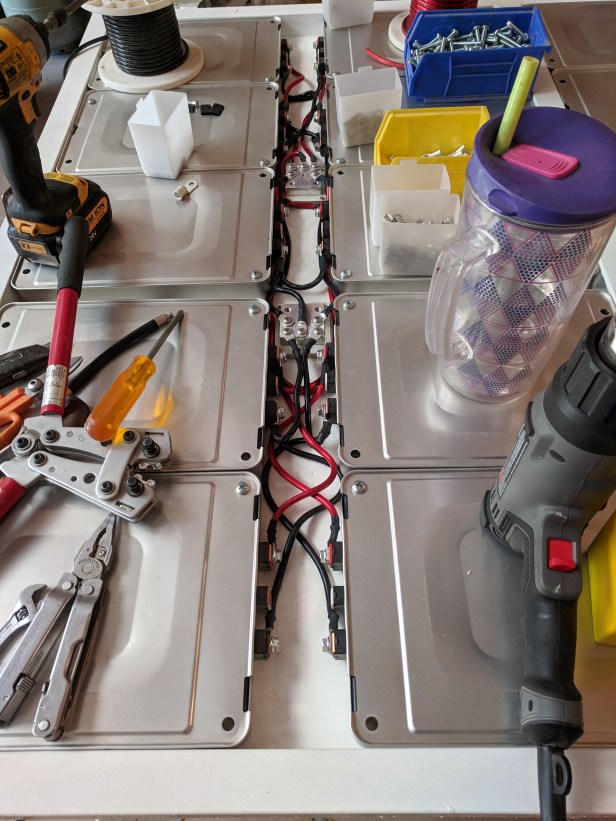
Each compartment contains buss bars to connect the parallel set using 1-8 gauge wire daisy chaining 2 packs, supporting up to 40 amps per pair or 20 amps per pack. The packs are rated at 90A max in the Leaf (45A/cell) but the camper design is much less demanding. The system can draw around 200A @ 26.25V nominal (or 20A/pack, 10A/cell). Buss bars of each of 3 sets of 10-2S2P packs and 1 set of 5-4P pack are connected using 2-2 gauge wires, supporting 220A through the battery.
The 4kw Samlex inverter is rated to draw 167A continuous, 209A intermittent (30min). Lithium batteries produce negligible heat either charging or discharging so there are no provisions for cooling other than conduction through the plywood bottom and truck bed (poor). There is also no provision for warming in cold weather. Lithium batteries can be damaged if charged when below freezing so that condition will have to be limited by the BMS. The BMS is exposed to the same temperature as the packs and will use internal sensors.

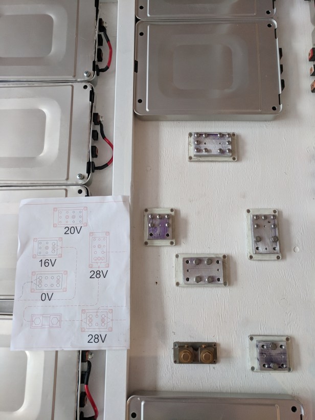
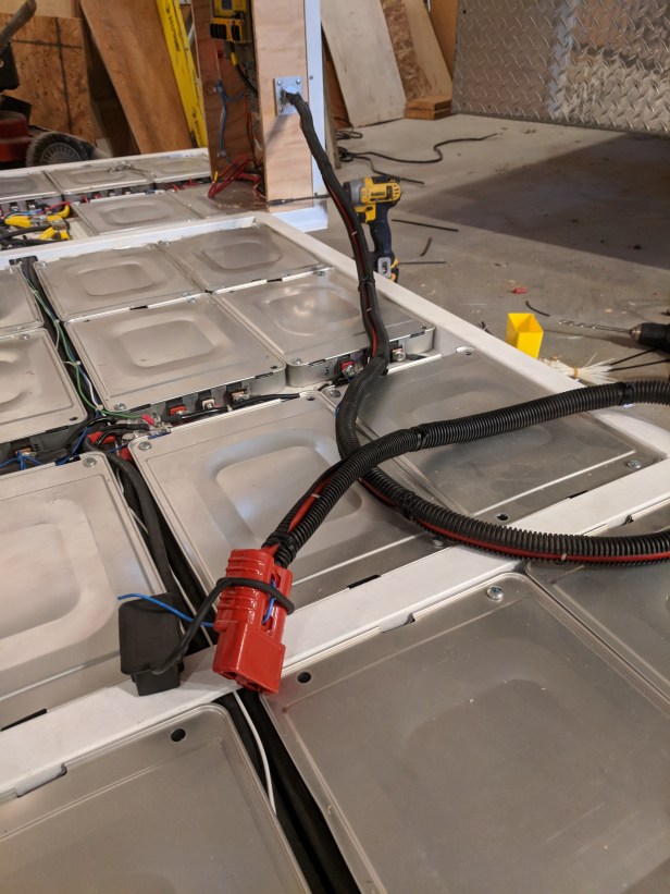
Pack connections are crimped, uninsulated terminals, covered with heat shrink tube, secured with M6 bolts. Bus bar connections are #10-24 screws into a 1/2″ thick aluminum block. Color coding conventions are not rigorously followed with colored wire but yellow heat shrink indicates the most positive end terminals. There are two, most positive buss bars. The end of the battery collection network (is a series of 4 buss bars – below). In addition to the buss bars, there is a 500A/75mV current shunt.
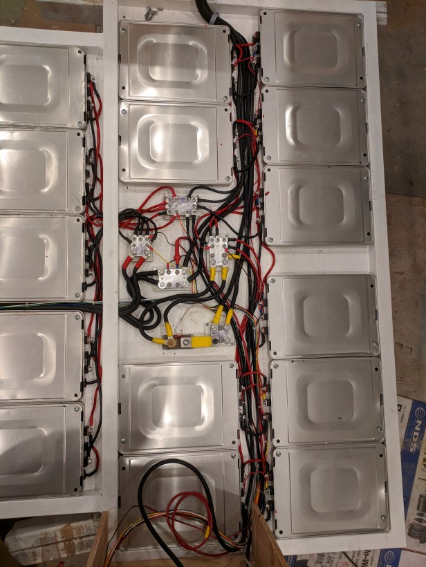
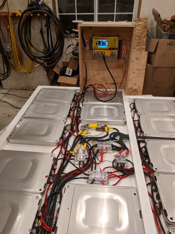
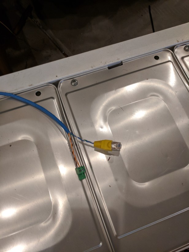
All external battery connections and management connections are made in the rear battery compartment which has a path for cables from both sides. The passenger side ‘stand-up’ compartment has the main power connector with 4-2 gauge cables on a 350A (gray) Anderson hermaphrodite connector. The connector mates the battery to a switch then to the inverter/charger. Also on the passenger side is a blue CAT5 cable connecting the BMS (on the driver side) to the inverter (on the passenger side) to communicate ‘OK to Invert’ and ‘OK to charge’.
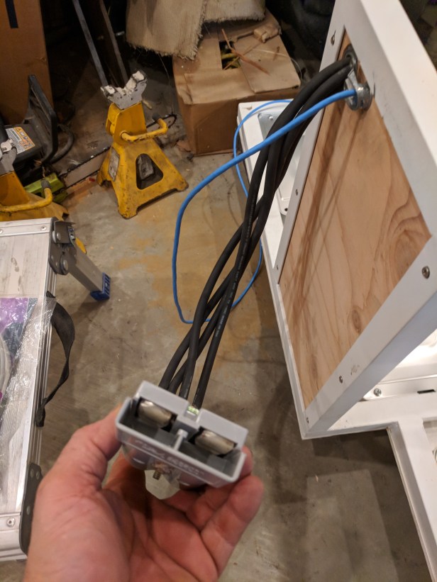
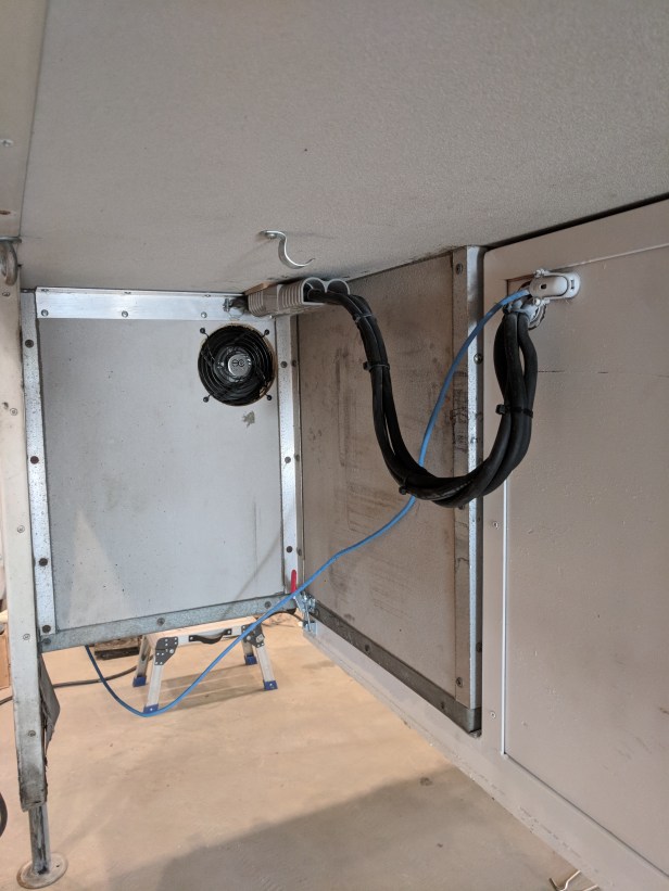
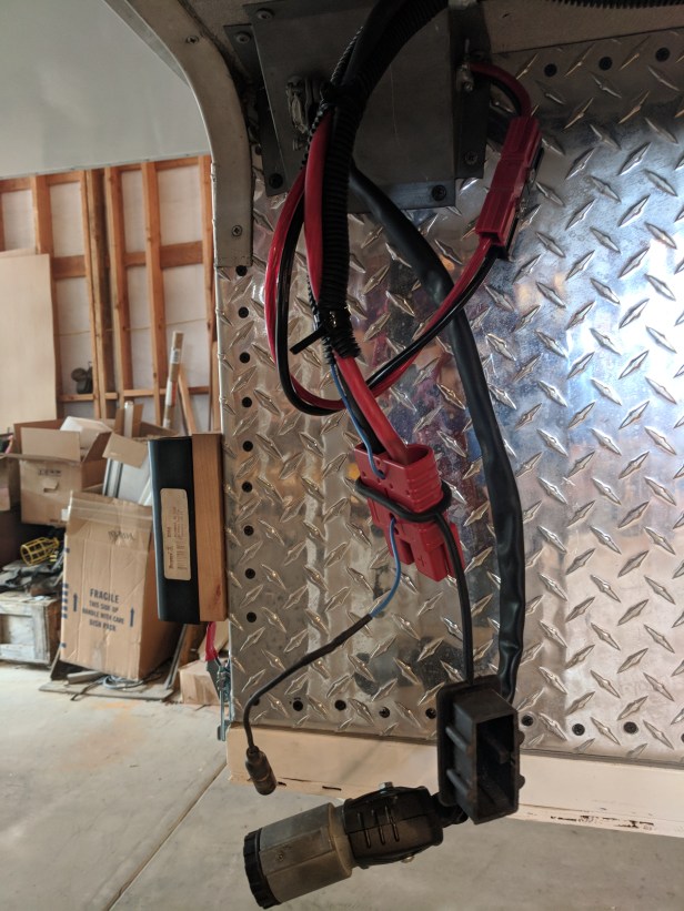
Leading forward from the driver’s side equipment compartment is an umbilical containing cable for 3 purposes; 2-4 gauge cables on a 175A (red) Anderson hermaphrodite connector provide the ability to link to a modified 29.6V@120A secondary vehicle alternator excited by the camper battery (14ga blue wire in the umbilical). Charging is controlled by an external voltage regulator in the engine compartment. To charge, from the alternator, there are multiple interlocks; 1) the BMS must allow charging, 2) a manual switch in the cab console must be ‘on’, 3) a thermostat on the alternator permits operation at less than 118C, 4) a relay closes only if the ignition is active. Also included in this umbilical are 2-8 gauge wires from the 40A DC-DC converter to provide 13.8VDC to the camper control panel for ’12V’ systems.
Battery Management Systems (BMS)
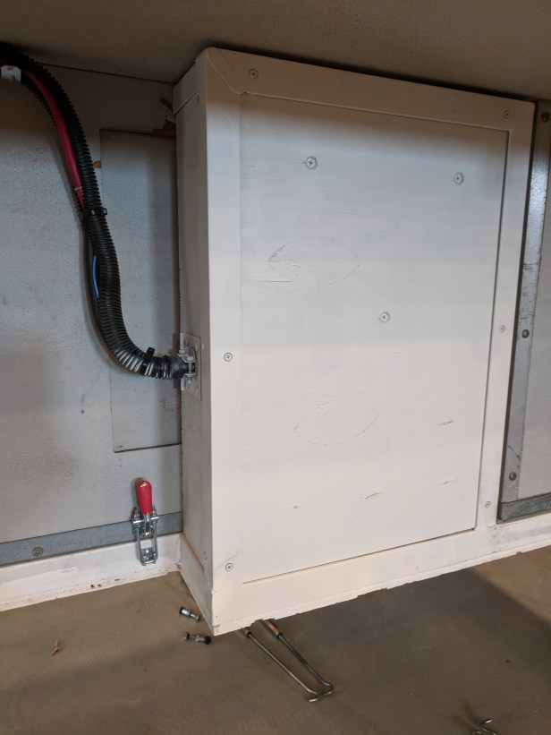
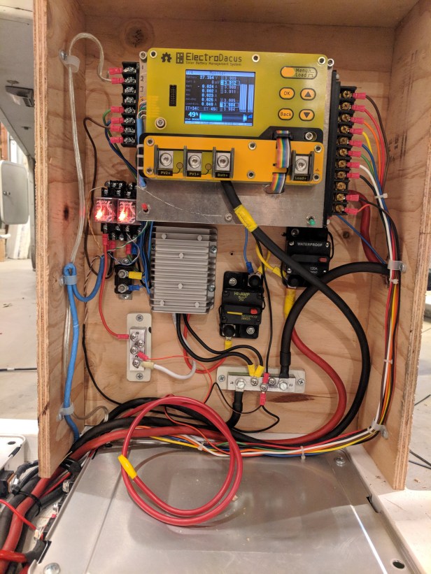
The BMS (yellow PCB with screen) is located in the driver’s side equipment compartment which is accessible through an existing ‘wheel well door’ inside the camper. Also included in this area is (going CCW); 2 relays to handle ‘stop charging’ and ‘stop discharging’ signals from the BMS, below the relays is a 10A auto-reset circuit breaker powering the alternator excitation, at 7 o’clock (close) is the 13.8V DC-DC converter (cast aluminum cooling fins), at 7 o’clock (far) is the 13.8V positive terminal buss, at 6 o’clock (near) is a 25A breaker for the DC-DC converter, at 6 o’clock (far) is the negative terminal buss bar, at 5 o’clock is the 125A breaker for second vehicle alternator.
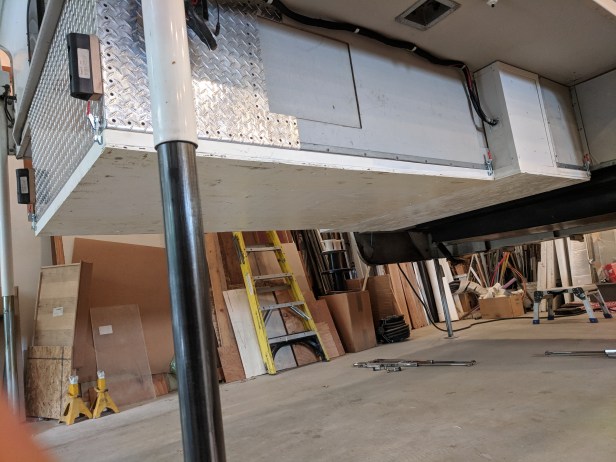
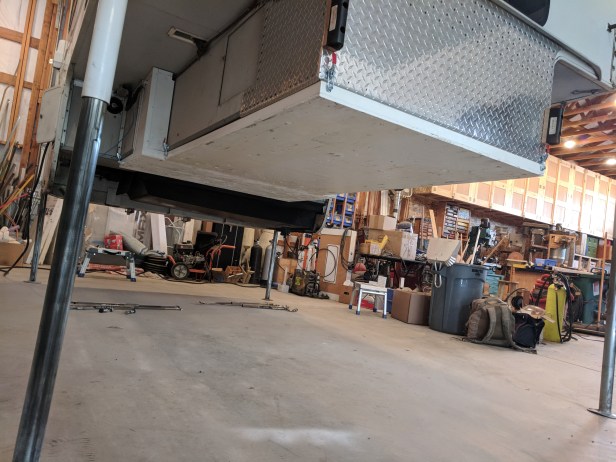
Mounting 400lbs to the Underside of the Camper
The entire pack is mounted to the bottom of the camper with 6-250lb draw latches. The entire pack can be removed or accessed by placing blocks under the camper and lowering the camper to the blocks. When resting on the blocks, the draw latches are released and the camper is raised. (NOTE: One problem I did have was the camper slid around on the battery at the front a little during rough road travels and broke some of the latches. I welded tabs to the side of the battery compartment frame to keep them from sliding and replaced the latches with a slightly different, more low profile, model).

Resources
Here’s a few resources that could be useful if you are a DIY-aholic like Steve or just a fan of everything power:
- Covering everything battery from basics to advanced: https://batteryuniversity.com/
- YouTube’s Will Prowse is a DIY Solar power guru with relative and educational content https://www.youtube.com/c/WillProwse. He does a good job of separating fact from hype and offers good advice.
- Our power inverter is made by Samlex. Visit their website for product specifics and under support there are videos and whitepapers available. https://www.samlexamerica.com/
- The BMS is probably the best one ‘not on the market’. http://electrodacus.com/ I bought it when it was still a kick starter but there is now a group helping the inventor, Dacian, to commercialize this product, which I heartily endorse.
Our Ford F350 Details
We have worked out the kinks in the 2004 Ford F350 and will continue to commission it to carry the new flatbed camper. Above, we cover the key priorities that went into the camper design. It’s great food for thought and a review of the trade offs to consider. You can also read more about our Ford F350 (a “franken” truck) background by clicking HERE.
Our Custom Camper Build on YouTube
If you enjoy personal travel stories and especially camping, follow this blog by entering your email below. You can also follow us on Instagram @WorkingOnExploring or @Maximus.4×4.camper, and subscribe to our WorkingOnExploring YouTube Channel on for our build and trip clips. Good luck on your own exploring and we’ll see you from the road somewhere soon!
Follow WorkingOnExploring travels and ongoing #SundayStills photo Challenge Posts
Delivered directly to your email inbox.
