
Lithium Battery & Solar Setup
My camper battery is a 24V nominal system of 35 Nissan leaf battery packs. Each pack contains 4 cells of Lithium Manganese Nickel Oxide (LMO) chemistry. They are arranged 7 cells in series and 20 cells in parallel (7S20P). The 35 packs contain 17.5kwh capacity and are equivalent to a 12V system containing 1166 usable Amp-hours. They were mounted in my Lance 1130, test bed camper in a 2″ tall ‘spacer’ attached to the underside of the camper. They were normally charged with 560w of solar but periodically I need or want to charge them more directly. I removed the on-board generator to save weight and space so my only other option is from an engine driven alternator.
The decision to add redundancy
Because I operate a 24V battery system, I had 2 choices, a DC-DC ‘boost’ converter based battery charger, drawing power from the 12V vehicle system, or a second alternator operating as a separate 24V system (I could also add a second 12V alternator solely to support the DC-DC charger but that seems silly). The DC-DC charger has the benefit of having microprocessor control of the charging cycle but at a much lower capacity (probably around 20A/500w). The increased draw of a large DC-DC charger on the 12V system would place high demand on the system only designed to operate the vehicle, possibly reducing the vehicle reliability. Adding a larger 12V alternator is possible but still with risk to the vehicle reliability. The potential conflicts with power demanded by the vehicle, the desire for redundancy and increased capacity led me to the second solution; install a second alternator operating at 24V and dedicate it to charging the battery.
2nd Alternator configuration
To get a picture of what I am about to discuss, below is a diagram of my system.

Primary Alternator’s Factory configuration
My truck is a 2004 F350 single rear wheel (SRW). It is worthwhile describing the factory configuration of the primary alternator and options to fully understand the potential of alternator power in the Ford 2004-07 6.0l diesel family. The stock primary alternator is 6G series, 110A, ‘small case’ model which has been determined to be inadequate and was upgraded to a 135A ‘large case’ model in 2005. I also made the upgrade to 135A. The alternator receives its drive from an 8 groove serpentine which also powers the power steering pump, water pump, cooling fan, and air conditioning pump. The factory pulley is 69mm (3.1:1 drive ratio). A 58mm, ‘overdrive’ pulley (3.7:1 ratio) was used for a while with the small case alternator with no apparent benefit. When upgrading to the large case alternator the stock 69mm pulley was retained. With all of the equipment being driven py one serpentine, it is pretty heavily loaded. Adding a significantly larger primary alternator may over stress the belt if a high demand was placed on it. Load induced failure of the 12V alternator’s serpentine would render the vehicle inoperable almost immediately. The same is not true of the secondary alternator because it is driven by an independent drive system. Its failure would only affect the ability to charge.
Ford Second Alternator Option
 Ford offers a second alternator option with a 120A ‘3G’ alternator (needs to be ‘flatter’ to fit in front of the passenger side head). The OEM design of the second alternator is to be activated by the ECU to produce power into the same 12V system as the primary but only generates when the primary alternator is so loaded as to reduce system voltage significantly. This is done to prevent the alternator from operating unless in extreme need as a means to improve fuel mileage. Some blog posts I have read of owners operating in this configuration, report that they feel it rarely, if ever, comes on. There is also no way of knowing if or when it does come on , or how much power it provides. In all, it sounds like a marginally effective ‘upgrade’ as controlled. See photo at right without fan or shroud. The primary 12V/135A alternator is at the top left, secondary 24V/120A alternator is at the bottom left. The secondary alternator is driven by a separate, 6 groove serpentine using a second balancer pulley with 3 idlers and its own tensioner, driving no other devices. The addition of the second alternator kit, requires a change in primary belt routing, adding an idler and 3″ in belt length. The second alternator mounting option seems ideal as long as it includes more comprehensive regulation. A 220A alternator in the same compact case, is also readily available through the aftermarket sources for ~$110.
The 2nd Alternator Kit
The set of parts needed to mount the second alternator was purchased as a ‘kit’ from a wrecked truck and sold on eBay for $175. It bolted up with only a little modification to the fan shroud to route the second belt.
How Does An Alternator Work?
First some notes on alternator operation.
1) Alternator ‘rated capacity’(in amps) is what it can put out at 6,000 alternator rpm (alternators are usually driven ~3x engine speed).
2) ‘Rated’ amperage is not their continuous duty capacity. Continuous duty capacity is limited by stator and diode bridge temperature which are hard to determine. A maximum 120C case temperature will be used as a safe limit. Using the 120C case temperature, the 120A rated alternator will deliver ~75A.
3) An alternator will overheat and burn out if highly loaded (and lithium batteries will do exactly that). There are no ‘inherently safe control’ present in an automotive alternator to limit excessive amperage or temperature. The regulator only monitors and controls voltage. Since this alternator is nearly certain to charge at a high rate that will overheat it, it will need a control system that monitors temperature and reduces load when it overheats. Without these additional controls, directly charging lithium batteries will overheat and burnout the alternator in minutes.
4) As an alternator begins to overheat, the only safe way to reduce the load is to reduce the excitation to the rotor. This will reduce the output voltage and thereby amperage into a fixed resistance. If you were to just disconnect the main output lead with a switch, the instant ‘unloading’ of the alternator will instantly spike voltage (faster than the voltage regulator can compensate) and destroy the diodes. This is also why it is unwise to fuse the output lead. Over heat/current might burn out the alternator but cutting it off definitely will….
Alternators: The Basics
A note on control of alternators; The strength of the magnetic field and the speed of the alternator, determine the output (voltage). Since the speed is always varying with highway conditions, the only way to control the output is to vary the voltage to the rotating electromagnet. To do that, a ‘regulator’ measures the output voltage against the target voltage and increases or decreases pulses of electricity to the rotor (making the magnet stronger or weaker) to maintain a steady output voltage.
What I Needed to run my 12V Alternator as a 24V System
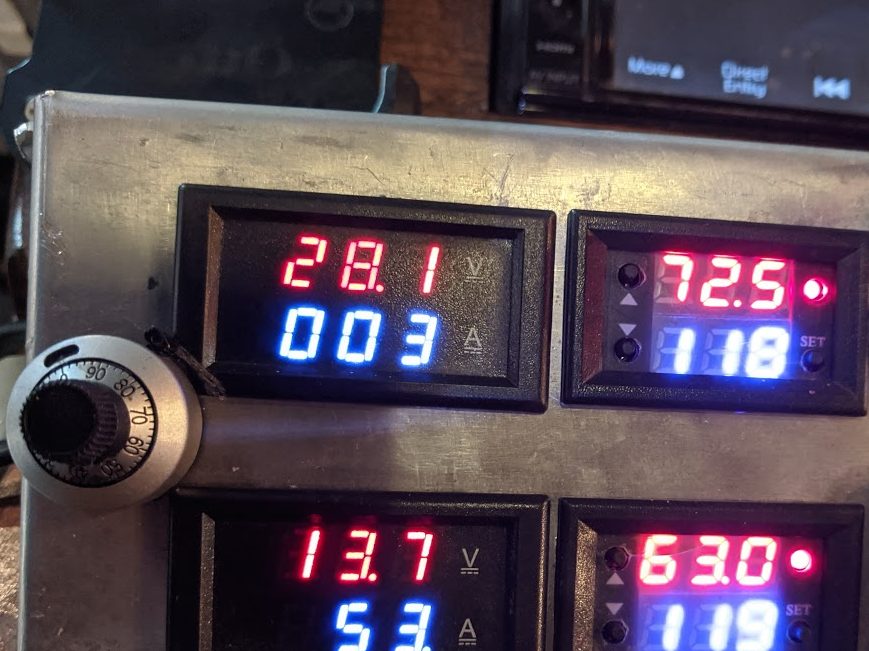
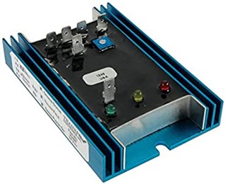 Since this is to be a 24V system and the alternator outputs 14V with a fixed internal regulator, the internal regulator needs to be bypassed. It cannot be removed since it also holds the brushes on the commutator. Brush leads need to be connect to an external 24V regulator that has an adjustable output such as a ‘Transpo V2400’ from ‘MotorCityReman.com’ (also on Amazon for $65). This manufacturer offers a different, 12V regulator with a ‘remote voltage adjust’ potentiometer on a cable but not a 24V one. To tune the charge rate, the voltage setting of the regulator will need to be adjusted periodically so the remote voltage adjust seems necessary. The V2400 embedded potentiometer was removed and replaced by a cabled 10k precision potentiometer mounted on the console. Using the power meter and temperature displays, an appropriate charge rate can be easily set. The micrometer scale on the potentiometer can also be calibrated to voltage output.
A note on types of regulators
There are two types of regulators for automotive style alternators, only one of which is in common use. The ‘voltage regulator’ compares voltage generated to a reference and adjusts excitation to maintain a steady output. It compensates for varying speed and load. The vehicle’s systems need a steady voltage to work properly, not because it is the best at battery charging,(because it is not). The second type is a ‘charging regulator’. It’s primary purpose is to charge batteries as rapidly as possible, according to the battery type and state of charge. While the ‘voltage’ regulator can do both, the ‘charging’ regulator practically cannot. It is more sophisticated but not intended to operate electrical equipment and batteries together. Doing so will ‘confuse’ the control algorithm. Sailboats generally operate in this fashion so this is where these regulators are found. Often sail boat engines have a small alternator with a voltage regulator for engine and control operation and a large alternator with a charging regulator. There are several manufacturers but Balmar and Mastervolt seem most common. A charging regulator manipulates battery voltage while monitoring current and temperature to tailor its output to meet the needs of the battery. It operates in ‘stages’ just like an external battery charger. They are programmed to specific battery parameters, delivering varying voltage and current through the phases of charging. Since they are initially operating at the maximum amperage possible, they also monitor alternator temperature, and slow charging if overheating occurs. Charging regulators are VERY expensive (often paired with special alternators designed for higher duty cycles than most land vehicle alternators). Like external chargers, many are not pre-set to charge lithium oxide types so would have to manually reprogram it….theoretically they are the best solution but I am opting for the $65 sub-optimal solution over the $400 one.
Connecting the External Regulator
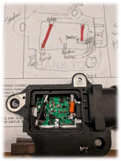
Connecting the external regulator is not difficult. Since the existing internal regulator operates by controlling the ground side of the brush and is an assembly that also holds the brushes, it cannot be removed, just bypassed. To bypass, open the case and break all existing connections to the internal regulation circuit. With an ohmmeter, find the 3 external leads to the connector and the 2 brush leads. The Transpo regulator works by controlling the positive excitation to the rotor. Four wires are connected to make the regulator work; 1) a voltage sense lead from the alternator output, 2) an alternator excitation wire from regulator output to the + brush terminal on the alternator plug, 3) A ground from the regulator 4) a 24V switched power into the regulator from the camper battery via a number of controls. Reference the diagram below; Inside the internal regulator, Of the the two brush leads, one is grounded and the other is routed to an external terminal. Wires need to be large enough to carry up to 8A. A pigtail was procured and wire added to reach the regulator installed under the steering column.
Ford’s original output lead wiring was 8ga, apparently anticipating an output under 60A. With a 120A rated alternator, the continuous duty rating was certainly well below the rated output, probably lower than 80A. DIrectly charging a lithium battery can demand excessive power. If allowed to simply operate at a voltage sufficient to reach full charge, it would cycle on/off on the thermostat at an amperage could exceed the rated capacity. It would take time to learn about the amperage/temperature relationship and a ‘significant gauge’ would be needed to survive the experiments. Surely 4 gauge cable connected between camper and truck with a 175A Anderson plug would suffice (~90-100A)? After 6 months of only experimenting with it a couple times, this turned out to be inadequate. It produced 150A on several occasions and melted the Anderson connector twice, once because a contact backed out. Since mounting the new camper, the 4 gauge cable has become 2 gauge and the Anderson connector eliminated. With the knowledge gained and modifications made, I am confident the controls will keep charging below the 75A experimentally found to be the continuous duty rating of the alternator. It would be ideal if the thermostat could only function as a fail-safe and not a normal means of control. Upgrading to a 220A alternator so that a continuous duty capacity of up to 140A is probable and compatible with the 2 ga cable. ‘Safe operation’ of the system involves using the on/off control of the regulator excitation to start and stop charging. Trimming the output potentiometer is how output amperage will be adjusted for a given battery state. A number of related circuits have the ability to stop charging. All operate in series on the wire that brings the 24V excitation from the battery to the regulator.
- The Battery Management System (BMS) must be able to ‘authorize’ charging based on parameters set (Electrodacus SBMS120). The BMS has an internal solid state relay that controls an external 24V/10A coil relay. The SSR is closed (on) when charging is ‘OK’ and in turn, closes the external relay, passing excitation power.
- The excitation is only be delivered when the key is on, so an automotive is relay connected to the 12V ‘ignition’ (key on) circuit.
- Manual authorization to charge is given my activating a switch to the right of the alternator meters on the console. 950W of solar panels will keep batteries charged most of the time and only on a deliberate decision and manual intervention will permit the alternator to charge.
- Most importantly, a thermostat in the console displays operating temperature and limit temperature to allow/disallow charging, automatically. Low batteries have the ability to place a heavy demand on the charging system for hours, potentially grossly overheating the alternator if not regulated by temperature.

The 10k thermistor sensor is mounted on the alternator case in an aluminum block (clamped to the case in a drilled and tapped hole, see picture above right) directly over the stator laminations. It allows excitation until the alternator case reaches 120C, then it cuts it off till it drops back to 110C. 120C is a relatively safe temperature. Turning on and off the alternator to prevent overheating is something that would NOT WORK WITH A PRIMARY ALTERNATOR. I think it likely that vehicle systems would be severely affected by system voltage going from 13.5-14 with the alternator on to 12.2-12.4V (loaded battery) when off. Then again, new ‘smart alternator’ systems (2016 trucks and newer), typically only run 12.4V most of the time, but they are designed to handle it.

Hey Steve,
I am curious about your decision to bring out the star point of the Wye-connected alternator stator and connecting it through the full wave rectifier module to the DC output.
This is certainly not common practice, and I was wondering if there is something unusual about this application that I don’t understand that makes this desirable.
Thanks!
Gray
LikeLike
It was how the alternator was originally wired internally (3 phase, 4 wire with 8 diodes). I actually rewired it delta the first time (just 3 wires coming out to a 3 phase bridge) and it didn’t work right (I later found I had a shorted TVS on my regulator but that was after I had already rewired back to the original 3 phase/4 wire).
LikeLike
Hey Steve,
Another retired/retiring engineer, here, though of the electrical variety. I specialize in things that happen more than 100,000 times a second, so power engineering is largely new to me.
I am very impressed by your deep dive into alternators, so much better than what one usually finds in the RV/camper or motorhead communities.
I have 22′ school bus on a 2007 Ford E450 chassis that I am converting for camping. It has the 6.0L Powerstroke diesel engine, which I gather is what is on the rig you describe here.
As you know, the options for high output alternators for the stock auxiliary position are very limited because of space, and nobody seems to be making any after market dual alternator kits. I have found just one aftermarket alternator for this position, made by XTD. There are a number of options for the main position.
My thought was to install the XTD in the aux position when I add the dual alternator kit and then extend the harness from the main position alternator to the aux location, thus making it now the main alternator. The stock alternate alternator (110A) is apparently not really large enough to run the truck, but I presume the XTD (220A) would be.
This would allow me to install one of the more readily available high output alternators in the main position to charge the house battery.
I would probably do your hack of replacing the stock regulator with a more sophisticated regulator, such as the Balmar with an alternator thermal sensor. I would prefer it all to be automatic rather than manual. The engineer in me may regret this, but I don’t need something else to distract me from driving!
I look forward to going through the rest of your posts on the subject.
Thanks!
-Gray
LikeLiked by 1 person
Gary,
You have opened a (good) can of worms. I’ll try to make useful comments and if you want to go into a deeper dive, I’m happy to do so.
1) The placement of accessory equipment/routing for a E350 is different from an F350. I found this for the single alternator. https://cimg5.ibsrv.net/gimg/www.mbworld.org-vbulletin/1595×974/routing_diagram_of_poly_v_belt_1_e0d6c2987b60a25def36d5ae4bbcaebcf974eb03.jpg but Icant find a dual alternator.
2) The 110A alternator is a ‘small case’ 6G alternator and does indeed have poor performance (less than 50A continuous). HOWEVER, you should not have one. Ford switched from a 110A (I had one) to a 135A (‘large case’) in 2005 (I changed with no modifications) because of its poor performance so you should have a 135A which is a pretty good alternator (~75A continuous). The mounting (bolts and spacing) is the same between them but because the 135A’s case is a larger diameter, it can interfere in some mounts made for a small case. A minor amount of grinding beneath the alternator can relieve the interference.
3) I’m not sure what alternator is used for the second postion in your van but the trucks are not even the same generation. Mine uses a 4G.
4) Look on e-bay for an ‘2007 E450 dual alternator’ and find a wrecked vehicle. Junk yards sell parts all the time. They may only be advertising the alternator but it also means they have the whole vehicle with the entire drive mounting. Contact them and tell you want the WHOLE mounting kit (including bolts). Mine was $175.
5) Swapping the primary/secondary alternator roles is a GOOD IDEA. I wish I had done it because my larger auxiliary alternator has less cooling air.
6) Adding a second alternator that operates as the OEM intended REQUIRES that a ford dealer modify the ECU to tell it that it now has dual alternators. I recommend NOT doing this and running the second alternator separately (completely divorced from the vehicle electrical system) as a charging alternator with an external charging regulator (Such as a Balmar MC-618). You may find an MC614 on ebay and that is fine. The 618 has some external ports to communicate with smart shunt that you won’t (likely) need. Stock control logic of dual alternators does not run them equally. It requires the primary be maxed out before the auxiliary comes on.
7). A good source for alternators is DBelectrical.com Here is a 200A primary for your E450. https://www.dbelectrical.com/shop/#/pf:ss_fitment:FORD$253EMEDIUM$2520$2526$2520HEAVY-DUTY$2520TRUCK$253EE-SERIES$2520VANS$253E2007 (currently out of stock). I does not list the part for the secondary of a dual alternator system. These MAY be suitable for the vehicle as well (based on writing in the description). https://www.dbelectrical.com/shop/?search_query_adv=dual+alterantor+2007+E450&fallbackQuery=dual+alternator+2007+e450
8) Some questionable searches from Autozone turn up both the 6G 110A (small case) and 135A (large case) as primary and the 4G as secondary. Many alternators with all the right features will show up as ‘not compatible’ because they lack or have a different bolt on adapter on the B+ that can be purchased separately.
I think you are on the right track and hope I have helped you further along. Call me (949)-307-1268 if you want to talk this over. Or email direct at steve.hericks@gm,ail.com. Im in Gooding, ID (Mountian time zone) working on building a house so am available ~9AM-9PM every day.
LikeLike
Steve thanks for your quick response. Here is an article I found interesting: http://www.aeroelectric.com/articles/Alternator_Failures.pdf It states that interrupting the field current prevents load dumps. There are many silicon devices on the market (e.g.,, TVS diodes) which might have the capacity to snub the transients. I also found Sterling markets a protection device: https://sterling-power.com/products/alternator-open-circuit-protection-device.
This Victron link has a Balcor(?) external regulator which incorporates a temp sensor in the alternator to automatically reduce the current to prohibit high temperature burnout. https://youtu.be/jgoIocPgOug
FYI, my 2015 Leaf battery pack with 29K miles from OR was delivered 3 days ago so I am right behind you!
LikeLike
Load dump would be an important concern if the current from the alternator is interrupted. How do you protect against load dump?
LikeLike
It is a concern. Normally you should not have a breaker on the cable between alternator and battery. I do but is a double edged sword…..The only disconnect on the path between alternator and battery is a 150A breaker at the battery buss. It’s purpose is to insure the survival of the battery if the 2ga cable running along the frame were to short (my biggest concern because a battery fire would consume the whole vehicle). It could potentially trip if the alternator were to exceed 150A, which it absolutely can and I’m sure would kill the alternator if it did. My manual trimming of the alternator output is my defense. I set it when I turn the alternator (rarely) to around 100-110A. My cable capacity is 140A. I only charge with the alternator, never run anything when I’m charging so I am in control of the alternator output, which I can always monitor on my console gauge. Alternator control is only by cutting the 24v power to the regulator, either by manual switch on the console, thermostat on the console or by BMS relay. The alternator is only about $110, so as a last resort, it’s an expensive fuse.
LikeLike
Steve thanks for your quick response. Here is an article I found interesting: http://www.aeroelectric.com/articles/Alternator_Failures.pdf It states that interrupting the field current prevents load dumps. There are many silicon devices on the market (e.g.,, TVS diodes) which might have the capacity to snub the transients. I also found Sterling markets a protection device: https://sterling-power.com/products/alternator-open-circuit-protection-device.
FYI, my 2015 Leaf battery pack with 29K miles from OR was delivered 3 days ago so I am right behind you!
LikeLike
Jim,
Sorry I missed replying to your comment. We’ve been heading to the backcountry to beat the heat quite often lately and have not had enough access to cell signal to keep up..
You are correct that interrupting field current is the ONLY correct way to manage the alternator output but is not related to a load dump and cannot prevent one. Let me explain; Cutting the alternator output connection, under load, to the load or battery is the cause of a dump (they are different and a battery disconnection is the fatal one). Even if the field current was stopped at the same time as the output connection was cut, there is ‘magnetic saturation of the iron rotor that keeps generating for some time (probably hundreds of milliseconds to seconds) after it is cut off. If the alternator is disconnected from a damping source such as the battery, in this short time, the energy in the alternator is still generated with nowhere to go, and voltage skyrockets. The energy in such an event is quite large.
I enjoyed reading the aero article. It’s interesting to see that the aircraft and boat community use alternators significantly different than the automotive. I have no experience with the small aircraft industry so was unaware of how they were controlling and using external regulators. The automotive has clearly gone the ‘dummy-proof route with internal regulators, controlled by the ECU to prevent load dumps that are made possible with other systems with manual controls.
I am a fan of all things Sterling and was aware of this device. I worked for 2-1/2 years making specialty aerospace electrical connectors which included a lot of ‘electromagnetic pulse’ resistant types (for military aircraft that drop nuclear weapons) with TVS diodes inside. The Stirling device appears to be little more than a sensing circuit to detect elevated voltage and operate the alarm contacts while the TVS diode shunts high voltage to the ground. This is the basic operational concept of the AC line ‘surge suppressors’.
It would certainly improve the chances of saving the VR/diodes from a pulse in a ‘normal’ load environment. IMHO both the voltage and current coming from the alternator windings on a high-level load dump are unlikely to be saved by this device. Most TVS suppression is for fairly low energy level events because their sources are typical ‘noise’, induction, or nuisance level. Because this dump event will come from operating at 2-3x ‘normal’, (likely near the maximum capacity of the alternator) and is SO CLOSE the the VR/diodes with no connection to anything else that could bleed off some of it.
LikeLike