
Episode 16 Video
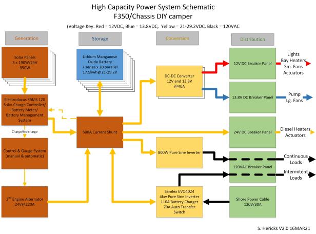
Although we’d migrated the large battery and power components before we hit the road for our shakedown trip, the power system remained incomplete. Now we finally have completed the solar installation! This video shows you the full power system details including the components used, how the fairing which surrounds the solar panels safely is fabricated, and how the big battery migration from old camper to the new rig was done. Below, I’ve also included the Power System Schematic.
What’s next?
Phase 2 of the rig work is continuing, still. We observed when the camper was dry, the 400lb power bay created a weight distribution problem that’ll only get worse once the AC and spare tire also get installed on the driver’s side of the camper. Now a redesign is underway which will change a the large battery location from the power bay to an inside, center position. That work has started (not shown in this video) and should be completed within a few days…then the water system and shower work can begin (finally).
If you enjoy personal travel stories and especially camping, follow this blog by entering your email below. You can also follow us on Instagram @WorkingOnExploring or @Maximus.4×4.camper, and subscribe to our WorkingOnExploring YouTube Channel on for our build and trip clips. Good luck on your own exploring and we’ll see you from the road somewhere soon!
Follow WorkingOnExploring travels and ongoing #SundayStills photo Challenge Posts
Delivered directly to your email inbox.

Hi Steve,
I’m planning to install a Renogy 30 amp DC-DC charger in our 2020 Ram 3500 with 180 amp alternator to refill our Adventurer 89RB’s lead acid 6v deep cycle golf cart batteries. I was going to follow the manufacturer wiring recommendations but noticed you suggest not connecting to the truck battery but rather directly to the alternator, which I will do. As you can probably tell, our system is very simple and low capacity to what you’ve done but I’d like to make sure I’m planning a well thought out install so thought I’d check if you had any other thoughts or critique? I was going to use 4awg jumper cables with a 175 amp Anderson connector, like you mentioned above, to allow removal of the camper when we are just using the truck alone. Also was going to follow manufacturer recommendation for inline fuses (60 amp for input to the charger and 50 amp on the output wires). What do you think?
LikeLike
This may seem long-winded and I hope you can stick with me;
The correct selection of cable and fuse is not simple and charger manufacturers typically over-size cable and undersize fuses so they can never be blamed for a failure. This can cost a lot of money in cable. I will run the calculations and provide references here because 4AWG cable is big and expensive;
1) The table of absolute wire ampacities by insulation rating (this is just to define a minimum wire limit) : https://www.bluesea.com/support/reference/529/Allowable_Amperage_in_Conductors_-_Wire_Sizing_Chart. Shows that assuming you have 90C or higher wire insulation, 14GA wire could actually work, but due to heat in the engine bay and possibly a confined space the charger heats up, 12AWG would be safer…….. Be sure that since your input wire will be in the engine compartment that you use at least 75C rated wire (printed on the insulation)
2 )The other criteria you have to contend with is voltage drop which is more important to propper operation than safety. https://www.bluesea.com/resources/1437. Calculations for both sides of the charger should be done separately. Assuming your (30A output) charger is located in the camper, its output (cable length is based on the length of BOTH wires or round trip @30A) distance to the battery is short (less than 10ft total or 5ft each wire?). Because this is a charging application and the ability of the charger to detect voltages at both batteries is important, use 3% voltage drop chart. By the chart, a 10AWG wire is satisfactory (charger to camper battery). Assuming the engine to charger leg is longer but less than 30ft (round trip?). The amperage on the input to the charger is higher than the output because of charger efficiency and low input voltage. Calculating the worst-case INPUT amperage we have to work backward from the output, (output is 30A @ ~14.4V = 432W) so the output is 432W/90% efficiency so input power is around 480W. Assuming you have a variable voltage alternator that can operate at a minimum of 12.4V, to deliver 480W@12.4V = 38.7A(max input current). 4AWG will offer less than 3% voltage drop and seems appropriate.
3) Fusing should be done to ensure that the fuse can never operate any normal load the charger can deliver YET still not more than 150% of the cable capacity (ABYC requirement). Since your fuses a both larger than the respective cable amperage, not make sure they are not too big for the cable. Cable absolute capacity (first chart) of 10AWG, not in engine spaces is 55A (x 150% = 82.5A max fuse limit). Also, and this is a bit sticky, understanding fuse capacity (NOT rating) is important. Assuming your fuse is NOT an ANL type, a 50A fuse actually functions around 130% or 65A. Since 65A is less than the 82.5A fuse limit, this is an acceptable fuse. Doing the same for the 4AWG output is; from chart 1, 4AWG ‘in engine spaces’ has a capacity of 135A (x 150% = 202.5A fuse limit). Since your recommend input fuse is 60A (rated) which has an actual capacity of 60A x 130% = 78A. This fuse is also acceptable.
We are almost done…..IF YOU ARE PLANNING ON USING ANL FUSES……use this chart (link below) to determine actual capacity. They are not like every other fuse where you can assume 130% capacity. https://www.bluesea.com/support/articles/Circuit_Protection/95/Choosing_Circuit_Protection
Using this chart, a 50A ANL fuse has a capacity of 120A (240%) and a 60A ANL fuse has a capacity of 130A (217%). Checking these against your limits you will find that the output fuse is TOO BIG but the input fuse is OK. If you were want to use ANL fuses, there is not a small enough ANL fuse made to be in range for the 10AWG output wire. FLATLY, ANL fuses are problematic. It is best to not use them even though they are widely available and inexpensive.
Using 175A Anderson connectors; 175A connectors seem (and technically are) oversized for the amperage being used but ARE appropriate for the (large) cable being used, MAKE SURE to get the right size contacts with sockets for 4AWG wire. These connectors are often sold as kits (2 shells and 4 contacts). Contacts come sized for the wire gauge being used (there are different contacts with sockets for EVERY wire gauge). Do not assume a 2AWG socket is bigger but ‘close enough’ to 4AWG. It is NOT OK. Buying with too large a contact socket presents poor conductivity/crimping problems. You CAN get sizing sleeves to reduce a 2AWG socket to accept 4AWG wire but these are not common. ALSO, you need the right crimper to make the connections (as you also do on the alternator lugs). This crimper is inexpensive and works on the sizes in question. https://www.amazon.com/gp/product/B017S9EINA/ref=ppx_yo_dt_b_search_asin_title?ie=UTF8&psc=1.
This comment about proper terminal socket sizing also applies to (ring) terminal lugs.
Last comment. The reason I recommend attaching charger leads directly to the alternator is because the cable from the alternator to the vehicle starting battery is most often not large enough to sustain as much constant power as your alternator will deliver with a charger in operation. Your charger demand will be constant (*up to 38.7A) and for a long duration which the vehicle manufacturer did not anticipate. If you feel compelled to follow the charger manufacturer recommendations to attach charger input cables at the starting battery, you should upsize the alternator B+ cable approximately to the next size larger than your charger input (in your case, a 2AWG).
LikeLike
This is amazing info Steve, I have read it once and will re-read it again later to make sure I process everything in appropriate detail, and I plan to follow the modifications you have outlined herein. Thank you again for sharing your expertise! 🙂
LikeLiked by 1 person
Happy to help. As it happens, I was helping another follower wanting to put in a 60A charger this afternoon.
LikeLike
I’m trying to figure out if using a second alternator is advisable for a truck camper setup. I intend to buy a Bundutec Roadrunner for my F350 1 ton. I had been also intending to install a Nations secondary alternator kit to help charge a Lithionics 630a/h battery. After reading your articles here and on Truck Camper Adventure, I’m wondering if that’s advisable. I’ve looked at this schematic and note that it includes fuses between the alternator and battery, which you advise against. The Balmar regulator seems able to protect the alternator against over-voltage and and over-temperature, but not against the other parameters that Lithionics uses in the BMS. And then there seems to be a basic question of what happens when the camper is unloaded? I’m not sure the camper could be disconnected. Any thoughts you have would be welcome.
Christin Hale
Massachusetts
LikeLike
Hi … we’ve been wandering out of cell service off and on for a couple of weeks and I (Cheryl) just saw your question. Steve will be around tomorrow and can get back to you soon!
LikeLike
Fantastic!
LikeLike
Christin,
Sorry for the tardy response. We have been in the backcountry and I have been down with a cold, so we have been negligent in checking on comments.
I think your plans would work fine with some consideration;
Thoughts in no particular order,
1) When I had my Lance in the truck bed and took it on and off regularly, I had a 175A Andeson Power Pole connector set on 4AWG welding cable (I use 2AWG now with no connector) that made it easy to connect and disconnect. I think that would work well in your case too. They also make a 350A version if you feel you want more insurance. I would not run a 175A connnector at more than 80% capacity continuously (more than a couple hours).
2) I looked at the lithionics battery info. They do offer the battery with or without internal BMS. It appears incapable of controling ANY external devices with their BMS, either in an internal or external version. If you want to explicitly control overcharging with your alternator, I would opt for some one elses. You need the BMS to be able to cut power (~4-8A/14V) to the VR. I use Electrodacus because it allows control of 2 external devices.
This is the problem with batteries with simple or internal BMS. They just use FETs to switch the main power on or off in abnormal or limit events. It protects the battery but is a dangerous (for the equipment) method of controlling. One thing you can’t do (without a high likelihood of damage) to your alternator, is cut off the load. This is THE problem with all ‘drop in’ battery options.
What you CAN do is to use your voltage regulator (Balmar Max Charge is programmable to do this) to charge to a maximum voltage below what the battery max that would trigger the ‘over voltage’ protection. Specifically, Set the VR to 14.4V when the battery max is 14.6. This works if everything operates normally but provides no protection if something goes wrong. This also means that you never get a ‘full’ charge from your alternator but that is fine for the battery as long as youre ok with a small capacity reduction.
I never attempt to achieve a full charge from the alternator. Let the Solar top it off.
3) Strategy for fusing the alternator; Overload protection devices (OPD) are there to protect the wire. There are two conditions OPD are designed to protect against; faults (shorts) and overloads. Because the cabling should be sized large enough that the alternator can never ‘overload’ the cable, shorts are the remaining reason. The lithium battery has so much energy that if the cable to the alternator were to ground on the frame, it is likely to set fire to the whole vehicle. This is the reson for using OPD that is normally not recommended. I recommend using OPD that is the next size larger than the peak (rated) capacity of the alternator and located near the battery (your main battery fuse may also be adequate protection) . This should be able to guarantee that it never trips because of current generated by the alterantor (common OPD tyicallly trips at 130-135% of rating except ANL fuses which are much higher), and only trips on a short (which is easily capable of a current 3-10x the alternator). In that way, there is no fear it could ‘unload’ and destroy the alternator on normal or even abnormal operation.
LikeLike
Thanks! Would alternative be to run the dedicated alternator to a second chassis battery first, then to a dc/dc charger, then to the lithium bank? I could still use the Balmar regulator to limit voltage, but the dc/dc charger would also allow me to limit current too and keep the alternator at or below its dut rating. Unless I’m wrong. I’ve been known to be wrong…………..lol. That would also solve the problem of having the Nations alternator running with no load when the camper is disconnected, wouldn’t it?
LikeLike
In short, Yes, that would work. However, I would not do it and I don’t think you will be happy with the charge rate/time. There are shortcomings and considerations (aren’t there always?)
1) Running a 12V alternator to power a DC-DC charger (40A is about the biggest) is a perfectly fine low-power alternative and fine if you have a small(er) battery. You do not. DC-DC chargers are great but they are not powerful enough to charge a large battery in a reasonable amount of time. THE reason for direct charging is to produce more power to achieve a charge over a shorter period. A 640Ah (x12.6V nom) is 8kWh+ of capacity. Charging @40A x ~14V delivers 560W. It would take 14+ hours to recharge….that’s a lot of driving.
2) It would be of no value to use a Balmar regulator in a system with a DC-DC charger. Your 12V LA ‘local’ battery is just there for stability. It is necessary but your DC-DC charger does not need a stable input voltage of any kind. They will typically work on 10.5-16V (and handle rapidly varying input voltage as well).
3) If you’re running a dedicated 12V alternator to a local battery to a DC-DC charger to your lithium, there will be a steady load on the alternator as the charger is the sole load and it will run at max almost till the end. That demand will be far less than its steady-state alternator capability. Assume a 40A charger producing 14.6V (the max output) = 584W (output). Assuming a 90% charger efficiency, the Input load is (584w/13.8V/.9) = 47A@13.8V. You can assume the continuous duty rating of an alternator is half its peak. At this, you could do all your charging with a 100A alternator. I presume you intend to go bigger…..and will need to go bigger to satisfy your battery debt.
In trying to figure out what you want to do, 1) go back and figure out how much power you expect to use between drives. (if you assume half, then 4kwh will be your battery debt.) 2) figure out what your average drive time will be to recover that power. If 3 hours seems enough, you need to recover 1.3kw per hour. At 13.8V, you need about 100A of charge.
Using YOUR numbers will tell you how fast you need to charge. From that, you can figure out what equipment you need to use.
Scott at ‘@Stonyboot’ runs 2-40A chargers on 2-220A alternators (factory ‘snow plow package’) with 300-360Ah of lithium (can’t recall exactly). I would not run chargers in parallel unless the manufacture tells you its OK (Scott did not ask). Its working for him but I would not expect it to work universally. DC-DC chargers need to sense battery voltage. With 2 chargers feeding the same battery, they can’t do it. There may be some charger networking/stacking ability from some manufacturers but I am not specifically aware of any. Scotts are not networked, they just happen to work….(for him at least).
LikeLiked by 1 person